(c) 2002 Jörg Hohensohn last change 05/24/2002
Preface
I’ve been
too much of a perfectionist with this. Please take my possible criticism with a
grain of salt. Plus, being from Germany, English is not my mother tongue. I can
express myself, but possess no particular writing skills. So the reading my be
dull to you, and often I need some wore words to come to the point.
In this
article I’m describing my modifications on an Amphony 1000 headphone,
particulary the DAC part I built. Although I give out this information for
free, I still reserve my rights on it. You’re welcome to use it for private
purpose, but not for business.
Introduction
Since quite
some years I have an unfulfilled product wish: An audiophile quality wireless
headphone. A top of the line headphone where you don’t notice the absence of
the cable, sound-wise I mean. This would require a digital transmission.
As a
teenager I happened to get a used Jecklin Float Electrostat, an old model. But
I enjoyed listening to it very much, the precise highs were unsurpassed (and at
that age I was most able to enjoy them). It lacked some bass, though. The
Jecklin is now in bad shape, with the cushion foam worn out and rotten, plus is
doesn’t reach the volume any more, with one side even weaker than the other. So
right now I’m without a true reference headphone. I had a Grado SR80 for mobile
listening, now replaced by a Koss Porta Pro, but that’s a different league. I’m
telling this for you to get an idea of my expectations.
There are a
few upper class digital wireless headphones on the market, I tried some of
them:
- Sennheiser IS850: Was built in low volume and
has infrared transmission, input is analog or digital. The company I work
for happened to engineer the central chip within. I wasn’t involved, but
because of this we have a sample which I could borrow for some weeks. It
sounds a great deal more precise than my Grados, coming nearer to the
Jecklin. The transducers are said to be from one of the top phones, I
suspect the HD590 or rather the HD600. Overall I liked it a lot, sound was
OK for me, but the infrared transmission was my killer criteria. It really
needs direct eyesight to the transmitter, although that is plastered with
about 50 LEDs. Unfortunately not practical for my usage, I figured I need
RF transmission.
- AKG Hearo 888/999: Features digital RF
transmission in the 400 or 900 MHz band. I presume they have to use audio
compression to squeeze it into that band, vaguely remember a salesguy at
the IFA show confirming that. Don’t like that idea very much. I’ve tested
it there, which turned out impossible because of the background show
noise, and because of the movie material they used. They were focusing on
a surround emulation rather than serious music listening. Later I tried
them again in a larger store, also not a quiet environment, but with my own
CD. Even there I noticed a hiss. To my opinion, even if the transmission
is digital, they screwed up by falling short with the amp in the phones. I
haven’t tested the 999 model. It’s said to be better, but I nowhere saw a
demo. Maybe I should have tried harder.
- Sony MDR-DS5100: Digital infrared like the
Sennheiser. It was on demo display in another large store, where I tried
it with whatever music they had on. The sound was nothing extraordinary, I
don’t remember much. They also focus on surround emulation.
With these
disappointments I was already thinking about a DIY project, well fearing that
it’s over my head. My favorite would have been a wireless electrostat. I
started to gather some material, today there are interesting components like
piezo transformers for the high voltage generation. But the efficiency is too
bad for battery powering.
For the
transmission, I started to look for those 2.4 GHz A/V links. The video part
would have enough bandwidth to carry an S/P DIF signal. But the receivers are
bulky and power-consuming.
About the
end of the year 2001 I happened to find the Amphony1000 phones in the web. They
use 2.4 GHz for uncompressed PCM transmission, exactly the technology I wanted.
The price ($130) is too modest for them to be audiophile, unless these guys
made miracles happen. You don’t get serious corded headphones for that price!
But I ordered them straight away because worst-case I was willing to scrap them
for the embedded transmission or had the feeling that replacing the transducers
can upgrade them.
Amphony 1000 Review
Main features:
- 2.4 GHz digital uncompressed
transmission
- 48 kHz 16 bit sampling
- Analog input to built-in ADC,
no S/P DIF
- Forward error correction (FEC,
redundant data against short interference)
- Weight: 266g w/o batteries, +
ca. 30-50g for 2 AA cells
Quality
The phones
arrived shortly before Christmas, my gift to myself. Right out of the box they
had some scratches on the outside, and on one of the earpads the thin material
was torn about one cm. I called the dealership, angry about probably getting
their worn out demo model, but they swore they’ve never touched it, offered to
return it to the manufacturer. But in fact I saved them the hassle, kept it
that way. For taking it apart it didn’t matter, but they may have a quality problem.
German engineering meets Chinese manufacturing, a culture clash?
Later I
found that on one of transducers the excess glue it was fixed with got spilled
into it, being dry it bridged the enclosure and the diaphragm. That’s a good
reason to sound bad.
The phones
look rather cheap from a closer look, like cordless phones for $25. The plastic
has burrs, the cans themselves are painted silver and appear imprecise. So no
reason to worry about my out-of-the-box scratches, it’ll get more anyway. The
battery compartments (one on each side, for an AA cell) don’t open too easily,
tend to stick. The cushioned earpads are covered with a very thin leather
imitation, rather sweaty. I guess Amphony took an existing El Cheapo phone and
upgraded it with their digital transmission technology?
The good
news is that they fit well. An elastic headband makes them weightless, and
there is no need to adjust anything. They rotate and tilt into place. The outer
diameter of the round cans is 9.5 cm, comparably modest.
Sound
I’m sorry
to have given them a devastating sound review in an earlier www.headwize.com
posting, my particular ones must have sounded crappy because of that glue
bridge. Later I was able to check another pair, sounding way better. So here’s
my revised review:
The sound
is “honest”, pretty natural without coloration. I always find voices to be most
challenging in terms of colorations, but they pass. (My favorite test material:
Suzanne Vega – Tom’s Diner, Tracy Chapman – Mountains o’ Things)
The highs
show decent resolution, but reveal the limitations of the transducers. Cymbals
can sound a lot more detailed. (Favorite test material: Ana Caram – Viola Fora de Moda)
The bass
goes down to about 30 Hz, below the transducers just can’t radiate sound. For
comparison, my Grado transducers are well audible at 20 Hz. So not too much in
for bass lovers.
The phones
may lack some volume, if you like to listen really loud (or have to, say as a
DJ). For me it was OK.
Overall I’m
surprised to find them sounding so well, considering the price tag and what
part of that might be left for the transducers. Don’t expect these to have true
audiophile qualities, that’s a different league. I would rank them close to my
Koss PortaPro, but without the Koss bass emphasis (which I never really liked,
BTW).
For those
interested: The transducers are 32 mm in diameter, the diaphragm may have 28 mm
of that.
Reception range
Under
“average” conditions I’d say it ranges about 10 m. The 2.4 GHz is in the
microwave range. So the signal likes to travel straight paths and suffers if
that’s blocked by metal. Microwaves are also absorbed by water and fat, which
is what people are made of (no offence!). Amphony gave the phones 2 antennas,
one in each can. I don’t know how effective that in fact is, but it sounds like
a good idea.
My flat is
almost covered by the transmission, I have a few holes though. It works well
into the next room, but may fail in the following. The failures are sometimes
nasty. Usually the phones instantly mute when they detect errors, but sometimes
can give you wild crackles. If you consider the digital transmission, you can
imagine that it can sound really bad if the numbers are screwed up.
There is no
channel switch for the transmission (maybe because they use up all available
bandwidth of the ISM band already), so you have no chance of avoiding others. I
have an analog 2.4 GHz A/V transmission which I have to shut off when using the
phones. Fortunately it doesn’t give audible interference, just reduces the
range. Bluetooth and WLAN also operate at 2.4 GHz, but I don’t know how they
interfere. In the future that band will likely be crowded.
What you
really have to avoid is operating a microwave oven nearby. Another reviewer
described the audible effect like “being hit by a Romulan disruptor beam”.
Well, luckily I haven’t been exposed to such yet. But well, it sounds loud and
unpleasant.
There is a
nice feature about the transmitter: It shuts itself down after a minute or so
if there is no input signal. So you don’t have to worry about switching it off
to avoid RF pollution. (It has no switch, anyway.)
Battery life
The phones
run on two AA cells. Mine came with a pair of half empty Chinese batteries.
I’ve never used them, I’m afraid they could leak. Probably most people will run
the phones from rechargeables. They take about 31 mA of current, volume doesn’t
really matter. I’ve put a pair of 1800 mAh NiMH cells in. You cannot exploit
the cells, because the phones stop working below 2.25 Volts or so. I haven’t
done stamina tests, but I’d guess they’re good for about 20 hours at max.
Amphony advertizes 100 hours, but you theoretically would need a 3 Ah cells
that keeps the voltage up above threshold. There are high performance primary
cells based on Lithium with 3Ah, but they cost a fortune.
Anyway,
battery consumption is low enough not to be bothered.
Technical+Inside
The
transmitter takes an analog stereo signal. The levelling is fixed, no manual
adjustment possible. The signal is sampled by a Burr-Brown (nowadays Texas
Instruments) PCM1801 ADC. That’s a low cost model. It may be possible to
upgrade this to a better one, but I rather went for an S/P DIF input later.
Then you could connect a DAT recorder as an external ADC, for example. The ADC
has 64 times oversampling and includes the nyquist lowpass filter, so
practically it can be directly fed with the signal. This is done via a
capacitor, the first in the signal path. In total it’s three, two more in the
receiver.
The digital
stream is subject to an FEC (forward error correction), which doubles the data
rate to a whopping 3 MBit/s. The added redundancy allows the receiver to
correct errors, if there are not too many. The FEC signal is available on a
cinch socket, it is meant to connect extra transmitters here to increase the
range by having extra “cells”.
The
receiver mixes the signal from its 2 antennas. The RF reception circuit is in
the left can, the right one hosts a digital part for the error correction and
the actual DAC and amp. Both PCBs are nicely shielded. The DAC being used is a
Philips TDA1311. It’s not featuring any oversampling whatsoever. The signal
coming out looks like a staircase. It has to be filtered externally, which is
done by the output amp. I didn’t analyze the circuit, but it’s probably
something like a 2nd order lowpass filter. There are still steps to
be seen on the final output signal, but surprisingly the sound doesn’t suffer
from it. Probable the transducers themselves are doing the remaining filtering
job.
The
single-ended output signal is coupled out with 220uF capacitors, the smallest I
ever saw. Together with the 24 Ohms impedance of the transducers this means a
low-frequency rolloff of 30 Hz.
Modifications
By now, I
spent a ridiculous amount of time into this project. It became sort of my model
train.
As I mentioned,
the obvious and most fruitful is to exchange the transducers. But since I
thought that to be the trivial part (not quite right, see later), I took a
different challenge first.
DAC+Amp Replacement
Because of
no oversampling and the filtering all in the analog domain, the frequency
response I measured is rather uneven, the phase response has a non-constant
group delay. I felt that this can be improved and searched for oversampling
DACs suitable for mobile equipment.
DAC Selection
A big
obstacle was the unusual system clock within the receiver. An oversampling DAC
needs an additional, higher frequency locked to the sampling frequency for its
filter logic. Normally, this master clock is 256 or 512 times the sampling
frequency (Fs), rarely 384 times. That’s what most DACs can be configured for.
The
receiver locks itself to the clock of the transmitter using a VCXO circuit.
That’s very good news, because a VCXO has way lower jitter than a PLL. But the
frequency is very odd, 6.528 MHz which is 136 times the sampling frequency, not
useful to standard DACs, bummer. This means I still would have to use a PLL to
generate 256*Fs and can’t benefit from the nice VCXO.
But I was
lucky to find a DAC which can handle it, and that is the poop of this
modification. The secret weapon is the Texas Instruments TLV320DAC23. It has an
odd mode to feature 44.1 kHz sampling with an input clock of 12 MHz from a USB
bus. Division tells this means master clock is 272*Fs. That number happened to
strike me while browsing the datasheet, it is twice of what I need. It can also
be programmed to use 6 MHz input, and then I get my 136*Fs, hooray!. A DAC with
it’s internal filtering doesn’t care about absolute frequencies, just the ratio
matters. So if I set it to above mode and feed a 6.528 MHz steam instead of 6
MHz, I’d get my desired 48 kHz output instead of 44.1 kHz. This doesn’t stress
the DAC at all, it can do up to 18.43 MHz and 96 kHz Fs.
It’s not
the best DAC in the world, but at least doesn’t require a PLL and is targeted
for mobile use. Power consumption is less than the original one. The high end
ones are really thirsty and require symmetric, split supply. Another
interesting feature of this DAC is that it includes electronic volume control
and a headphone amp! The downside is that it requires programming, via I2C or
SPI bus. An onboard controller is needed.
I’m a
software developer by profession (hardware developer by passion), so that
didn’t scare me too much. On a prototype board attached to the receiver, I
built my first test setup, see picture.
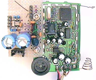
The two
DACs are side-by-side here, the new being the chip with the red and green
wires, the old is the DIL-8 chip on the original board. So I was able to
compare. The small chip on the left is another headphone amp (also from TI to
have it symmetric), which I used as inverting buffers to form a bridged output,
the 4-pin header next to it. This has the benefit of not needing output
capacitors and the doubles voltage swing gives quad power. I thought that might
be a good idea for a design that runs on 3 Volt supply, or 2.4 if rechargeables
used. The output below (3-pin header) is a classical one directly from the DAC,
and you easily notice it needs capacitors. I picked 1000uF for the low
frequencies.
The I2C bus
was controlled externally here. The top header connected the whole to my PC,
were some printer port hardware I built forms an I2C master. So I could test
the programming.
The results
were quite promising, the frequency response flat as Utah salt lake, the group
delay constant. I decided to carry on with a bridged amp, since it gave a nice
and powerful punch. The drawback of bridging is you get twice the distortions,
both amps add their share, but with today’s amps that’s no big deal. The
benefit is that you get almost immune to noise on the power supply. That later
became very useful, but at that time I didn’t know.
Microcontroller
For the
volume control, I decided to try the builtin electronic one controlled by
software. The idea was to use the existing pot (anything else would have
required mechanical work which usually looks amateurish) for an analog input of
the controller, which in turn can issue the proper I2C sequence to the DAC. I
can use both halves of the stereo pot in parallel, so I’m pretty much immune to
wiper failures which these cheap pots so often develop.
For a past
project, I have used a small 8-pin controller with onboard ADC (for analog
input) from the PIC family, a 12C671. But that is either UV-erased or OTP, which
was a pain. This time I wanted a flash controller, which can be programmed in
circuit. Microchip is really behind technology with their PIC line, only a few
feature Flash memory. For my really small 8 pin model, there was nothing
available.
This time I
chose an Atmel controller, ATtiny15L. It has a 10 bit analog input (well enough
for the possible 128 volume steps), Flash and EEPROM. The latter is nice for
altering settings without the need to recompile the software. I had to buildup
a toolchain for this controller, since I’ve never used Atmel before. On the Web
I found ICC Tiny from ImageCraft as a C compiler in a 30 days evaluation
version and PonyProg for actually programming the device, via a to be built
parallel port cable. (Again the parallel part, I’m glad my printer is connected
via USB.)
I was able
to complete the programming before the compiler expired. The remaining fine
tuning was possible via EEPROM settings, which PonyProg can do. A special thing
about this controller is that it contains no RAM. Everything has to be kept in
the 32 registers, which worked out for me.
Software operation
On
power-up, the controller sets up the DAC for the required modes, with the
initialization data being stored in EEPROM. Then it programs the watchdog timer
to reset the controller periodically and goes into a very low power sleep mode.
The average power consumption is neglible.
Within the
periodic wakeup, the controller applies a voltage across the potentiometer and
measures the voltage at the wiper. The pot only gets power during the
measurements, to save energy. My great trick, ha! If the wiper position has
changed, the volume is reprogrammed. As a very useful extra I use a floating
hysteresis for this measurements, so that a “nervous” ADC reading does not constantly
change the volume.
The
compiler had a catch for me: it clears all global variables (registers used as
such) on reset. The watchdog loop also is a reset, and I loose my previous
level to compare against. I had to patch this out of the compiled hex file,
can’t use the compiler output directly.
First real board
I made my
first PCB, which contains the circuitry of the prototyping board with the BTL
amp plus the controller. The whole is supposed to be a daughterboard ontop of
the original and still fits within the shielding. It takes the power supply and
digital audio pins from now vacant through-holes of the original board, from
which I removed the DAC and analog part. So most signals come and go with
straight pins from the original board, as you can see from the bottom view.
Only 3 wires have to be laid: 2 for the potentiometer, one for the clock. (the
empty holes below.)

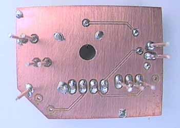
The DAC is
the one with the many pins, the controller is at the bottom (with the 5 ISP
pins for programming above it), the inverted BTL amp half at the right top.
This got
soldered into place and I hoped that’ll be it.
Second board
Unfortunately
the first shot wasn’t quite satisfactory. I noticed audible crossover
distortions behind the amps when loaded with low impedance, that went unnoticed
with the prototype. I did more measurements and found out that the TI headphone
amps are no good when loaded. Finally I redesigned the board to have a fully
external BTL amp. And I took the chance to improve the power layout. I still
use the headphone output because only that can be volume-controlled in
software, and I found it as good as the line output the DAC also has. Both
outputs have a residual noise (hiss) which is about the same magnitude as an
LSB, the faintest reproducible signal. My stationary CD player does better, has
less noise in that discipline. I’m afraid I have to live with that for this
DAC.
Below you
see the 2nd board ontop of the original:
 (click to get large view)
Digital Input
To fully
exploit the digital transmission, I wanted an S/P DIF input. That task was not
so hard, fortunately. The 3rd cinch socket of the transmitter (the
FEC output which I like supposedly most people don’t use) was crying to be my
digital in.
The
transmitter is the system’s clock master. It “dictates” the 48 kHz it uses to
sample the input. But anything attached to the digital in also requires to be
master. A sample rate converter (SRC) can bridge that gap. It would have been
to difficult, or rather impossible, to change the transmitter to be a slave.
Such SRCs are standard parts, and the CS8420 from Crystal Semiconductor also
contains an S/P DIF receiver. So all I need comes in one chip.
This time I
haven’t done a PCB, because the chip is in a standard SO package which fits on
available prototyping boards. Below is the hookup:
 (click to get large view)
Well, there
are two more chips on the board. The one that looks like a transistor is a
reset generator, and a very small 6 pin mux (left of the SRC) selects between
the data from the DAC or the S/P DIF data, based on whether there is a valid
signal. I didn’t like to drill a switch or so into the transmitter, therefore
the electronic selection. The digital in has priority. When a valid signal is
found there, it gets fed trough. Otherwise the analog input is used.
There was a
side project to equip my home CD player with a digital out, because it didn’t
have one yet. But that’s a different story.
With the
digital in I was able to really test the DAC part, because now I can be sure
about what signal reaches there. That’s how I did the LSB test. I have a homemade
test CD which contains computer-generated test signals. In fact I did the
digital in mod sometime during the DAC upgrade.
Transducers
That was
the last part, which I considered easy. The whole time I have been watching
Ebay for suitable broken or worn out phones with nice transducers. After the
DAC part was done and I had a mobile assembly of those two modules (RF and DAC)
again, I went to some local hifi stores to test headphones on it. The
salespeople looked a bit puzzled. It turned out to be Sennheiser HD600 against
Grado SRx25, with my old SR80s falling short behind those. My favorites would
have been the Senns, while the transducers are available as replacement parts
for a reasonable price ($40 apiece). But they’re 300 Ohms impedance, which doesn’t
really match my amp even in BTL mode. The volume didn’t have enough headroom.
Grados are 32 Ohms, perfect for me. But they don’t sell parts in Germany, and
new they’re quite expensive here, not very common. There’s no 2nd
hand market at Ebay Germany for those.
I decided
to scrap my SR80s, the most reasonable solution. Now I don’t have the upper-end
transducers I dreamed about, but maybe one day I get an opportunity for a used
SR125 or SR225.
The final
soundcheck with everything put together again was at first disappointing. The
Grado transducers suffer from not being in an open headphone any more. I was
partially expecting this, since they sound crappy when you hold the outside
closed with your hands while listening. A layer of damming wool (correct term?)
partially got me rid of the effect. I suspect the Amphony cabinet to have some
resonance, maybe I can improve that with a dampening coating on the inside.
Voices still sound colored, which the original transducers didn’t show. At
least the improvements are that my bass is lower and precise, and the highs are
as good as it can get with the SR80s. I consider this modification not yet
completed. More to follow on this chapter.
If anybody
has nice and low impedance transducers lying around, please get in contact with
me.
Earpads
I sweat
under the original ones, since they can’t breathe. During my Ebay days, I
cheaply acquired several replacement pads for other headphones of which I
thought they could be fitted. But none in fact did, what a foolish attempt. Anybody
in need of pads for Sony MDR-CD480/580/780/2000 Sennheiser HD560, Beyer DT220?
My very
latest modification was to tailor new pads out of velvet. Recently Amphony sent
me a free replacement set of earpads for my torn original, thanks! After
replacing my bad one, I carefully cut open the seams, took them apart to get
measures for a pattern. Two elliptic rings of fabric are needed to replace the
visible part, the thicker inner pleather backside can be reused, as well as the
foam.
The
tailoring effort is ridiculous, at least for me usually being far from those
tasks. It took me half a day per side. But likely the summed Ebay
searching/ordering was more. A sewing machine may help a lot, if it can be
precise enough on the elliptic shape. I have no experience with such, did the
sewing job by hand.
With the
second one I found a great trick to more accurately and cleanly process the
velvet: Before cutting, circle your marking with a glue that stays elastic when
dry. Soak about the bordering 2 mm meant to stay with it, the cut away side
doesn’t matter. Let it dry, then cut the shape. This way the sealed edges stay
perfect and are a lot easier to handle. With my first one I always had to be
very careful to avoid the fabric from falling apart. The glued edges will later
be invisibly hidden within the seams. Just make sure you don’t glue more than
about 3 mm inside.
The result
was better than I expected, I got the shape pretty well. Now I have velvet
pads, no sweating. They are also more quiet than the original material.
Ideas for the future
Power Regulator
It would be
possible to extend battery life with a step up switching regulator. That would
keep the supply voltage up while the battery voltage already goes way below. Or
it can give the option to use just one cell, saves same weight, or run from AAA
cells instead of AA.