The Alpine
M-Bus Protocol
Last
change: 2004/05/05 (link chapter)
Overview
The M-Bus
is the old connection between Alpine headunits and CD
changers, the DIN-style circular plug. I don’t know much about its history, usage
for other brands, etc. (Volvo and Sherwood are among it.) I just had to need to
hack it in order to connect an MP3-player instead of a changer to the radio, so
I started measuring. Below is what I found out with my gear (9294 head unit,
5952 changer), your mileage may vary.
Electrical Characteristics
The bus
uses a single wire and half duplex transmission. At both the radio and the CD
changer end it is pulled high to about 10 volts idle level, with resistors in
the range of 1800 Ohms. Both devices can now drive the bus low with their open
collector outputs.
So it is
not really TTL friendly. I used a piece of circuitry like below on my end, to
feed it into a microcontroller:
Logical Layer
The line
coding is unusual. It’s none of the textbook codes, instead some kind of pulse
width modulation. A short low pulse (about 0.6 ms) is a binary zero, a longer pulse (about 1.8 ms) is a one. The distance
between the pulses remains constant, about 3 ms. The
resulting baud rate is about 325 baud, fairly slow.
In other
words, a bit starts with a falling edge, then the line is held low for 0.6 or
1.8 ms. The next bit starts after 3 ms, if there is more.
Bits are
grouped to packets, with length always multiple of 4 bits. So it makes sense to
write down packets with hexadecimal digits. The most significant bit is
transmitted first, so they are in left to right reading order. A packet ends
when no more bits are transmitted back to back within the bit time, when the line stays
high.
The packets
I’ve seen are 12 to 64 bits long, 3 to 16 hex digits. The first digit (the
first 4 bit) is some kind of address, it is always ‘9’
if coming from the changer, and ‘1’ if coming from the head unit. The last
digit is a checksum. It took me quite a while to figure out how it is
calculated, but the end result is simple: XOR of all hex digits excluding the
checksum, add ‘1’ (may wrap from ‘F’ to ‘0’).
Here’s an
example of the most simple packet sent by the radio,
I’ve called it the ‘ping’ packet:
|
Hex description |
address |
command |
checksum |
|||||||||
|
Hex Digit |
1 |
8 |
A |
|||||||||
|
Binary Digit |
0 |
0 |
0 |
1 |
1 |
0 |
0 |
0 |
1 |
0 |
1 |
0 |
|
Bit description |
|
|
|
|
|
|
|
|
|
|
|
|
In the
following, I will use this style of table to document the packets I’ve seen. I
will omit the checksum, because for all packets containing data this will vary.
Command Reference
I cannot give
a complete reference, only what I’ve seen with my equipment. I have named the
commands arbitrary. Corrections and additions welcome.
Ping
|
Hex description |
address |
command |
||||||
|
Hex Digit |
1 |
8 |
||||||
|
Binary Digit |
0 |
0 |
0 |
1 |
1 |
0 |
0 |
0 |
|
Bit description |
|
|
|
|
|
|
|
|
This is
sent by the radio if nothing else is to by said and done, to keep the
communication alive. The expected response from the changer is ‘Ping OK’.
Ping OK
|
Hex description |
address |
command |
||||||
|
Hex Digit |
9 |
8 |
||||||
|
Binary Digit |
1 |
0 |
0 |
1 |
1 |
0 |
0 |
0 |
|
Bit description |
|
|
|
|
|
|
|
|
This is
sent by the changer in response to a ping packet.
I preferred
Excel for the “real” documentation of the commands, so here’s
the detailed reference. I have not made a documentation about the semantic of
the commands, sorry.
Tools
When I worked
on this, I made myself some tooling to tackle the bus.
M-Bus <->
RS232 Converter
The first
“product” is an Atmel microcontroller implementation
of the physical and logical layer. It can listen on the M-Bus side and send it
out again as a hex dump via RS232. Packets are separated with a linefeed. For
the other direction, it receives and collects hex dump chars from the RS232.
When a packet is “terminated” with a linefeed, it will be sent out to the
M-Bus.
For most
applications, this is all you need. The converter allows to talk with the M-Bus
via an RS232 link. A terminal program can be used for fist steps.
Hardware
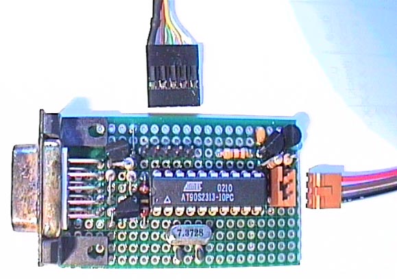
On the left
is the DB9 jack for RS232, right is a connector for the M-Bus (ground, bus,
12V). The M-Bus supplies the power. On the top is the connector for in-circuit
programming the board. The design is very straightforward. The Atmel 90S2313 is clocked by a 7.3728 MHz chrystal, which allows nice baudrate
generation. Default is 115200 Baud, but can be changed in the EEPROM space of
the controller. The transistors close to the BD9 jack are for level conversion
(no MAX232), on the upper right is a 5V regulator, beneath that the open
collector driver for the bus.
My
prototyping board is a little bit different than the schematics below
(free-hand drawn with Eagle PCB, not proofed), because I use my own non-standard
ISP connector. Below is compliant with the “official” STK200/300 programming
cable. There is a very simple cable variant for the printer port out somewhere
in the web (can’t find it right now) which does not require active components,
just a few resistors and diodes. That’s the kind I use.
The
transistors can be practically any small signal NPN type,
I just pulled some out of the box. Same goes for the diode D1. But D2 needs to
be a Zener diode with 4.7 Volts threshold. The
connections to the crystal pins should be short.
Feel free
to make a PCB layout from this and send me the results, the schematic files are
here. (Made with the freeware version of CadSoft Eagle)
Software
Here is the software running on my “M-Bus
Dongle”. It also compiles on an AT Mega8 device, if you prefer that. I have
compiled it with Gnu-C for Atmel. Hex files for both controllers and sources are
included. I use PonyProg
to program the hex files.
M-Bus Monitor Application
For
learning more about the bus, the terminal output is not so nice for humans. For
this reason, I made a (Windows MFC) application which displays the hex log
together with a readable interpretation, plus an icon indicating the source and
status, plus timestamp information. Credits for the serial communication class
go to Thierry
Schneider.
The
application first was a pure passive monitor, telling what’s going on at the
bus. Later it got a second mode (shown at work above), where it emulates a
changer, cheating the radio. With the changer class I learned what the headunit really wants to hear, versus what info from the
changer is babble.
Source and
executable for the program are here. I have
plenty of real-world logs for various changer states,
but from various phases of the project and not in a consistently documented
shape. Some have delta timestamps in the first column, some are very raw. I
hope it still helps.
Why Am I doing this?
Maybe
you’re curious why I went through all that trouble and give out all that info
and sources for free (I hope Alpine won’t mind). I have an ongoing project of
connecting an Archos mp3-player as an alternative to
the “real” changer. I’ve heavily searched the web for M-Bus info, but nobody
(except one guy to who’m I couldn’t get contact)
seemed to have hacked with the older Alpine gear. So I had to try it on my own.
Many other people did valuable stuff in their free time that was of good use to
me (like the Atmel tooling), so I’d like to give
something back to the community, hoping it can be reused. I’d kindly appreciate
a status notification if so (robot-cloaked email address: joergDOThohensohnATgmxDOTde).
Links
My postings
about it to the Archos Rockbox
group:
http://rockbox.haxx.se/mail/archive/rockbox-archive-2003-11/0476.shtml
http://rockbox.haxx.se/mail/archive/rockbox-archive-2004-01/0778.shtml
Marek Debowski made a controller box for his changer:
http://www.cdchangeren.prv.pl/
Later I
learned about this parallel activity (would have saved me a lot of work)
Mictronics
has links to various CD changer protocols:
http://www.mictronics.de/?page=cdc_proto